Page last modified: Apr 11 2022.
This document describes implementations of bottom occlusion due to silt and object occlusion due to marine growth. Simple examples are implemented by manipulating visual elements of the the model’s SDF (or URDF) links. The bottom occlusion example is extended to simulate damping effects on object motion caused by partial submergence in a viscous medium.
Visual demo
Visual bottom and object occlusion can be observed by using the following command:
roslaunch dave_demo_launch dave_simple_occlusion_demo.launch
The command will launch a Gazebo simulation similar to the one associated with the Bar Retrieval demo (in fact, this simulation’s RexRov vehicle can be controlled in exactly the same manner as the demo version). The differences are that the “grabbable bar” will be partially occluded by “silt”, and the scene includes a large “moss covered” cinderblock.
Because the occlusion effect is achieved by manipulating visual SDF elements, only those sensors and plugins that rely on the rendering pipeline will be affected. In particular, the Gazebo GPURaySensor and CameraSensor and DepthCameraSensor will experience occlusion. Senors and plugins that rely on simulation’s physics engine such as the Gazebo RaySensor and SonarSensor, interact with the collision SDV elements and are not affected. Other models, including vehicles and physical manipulators, will “penetrate” the visual occlusion and interact with the collision model.
Bottom occlusion:
Upon launching the simulation, the “grabbable bar” and RexRov vehicle will be situated as depicted in the following image:
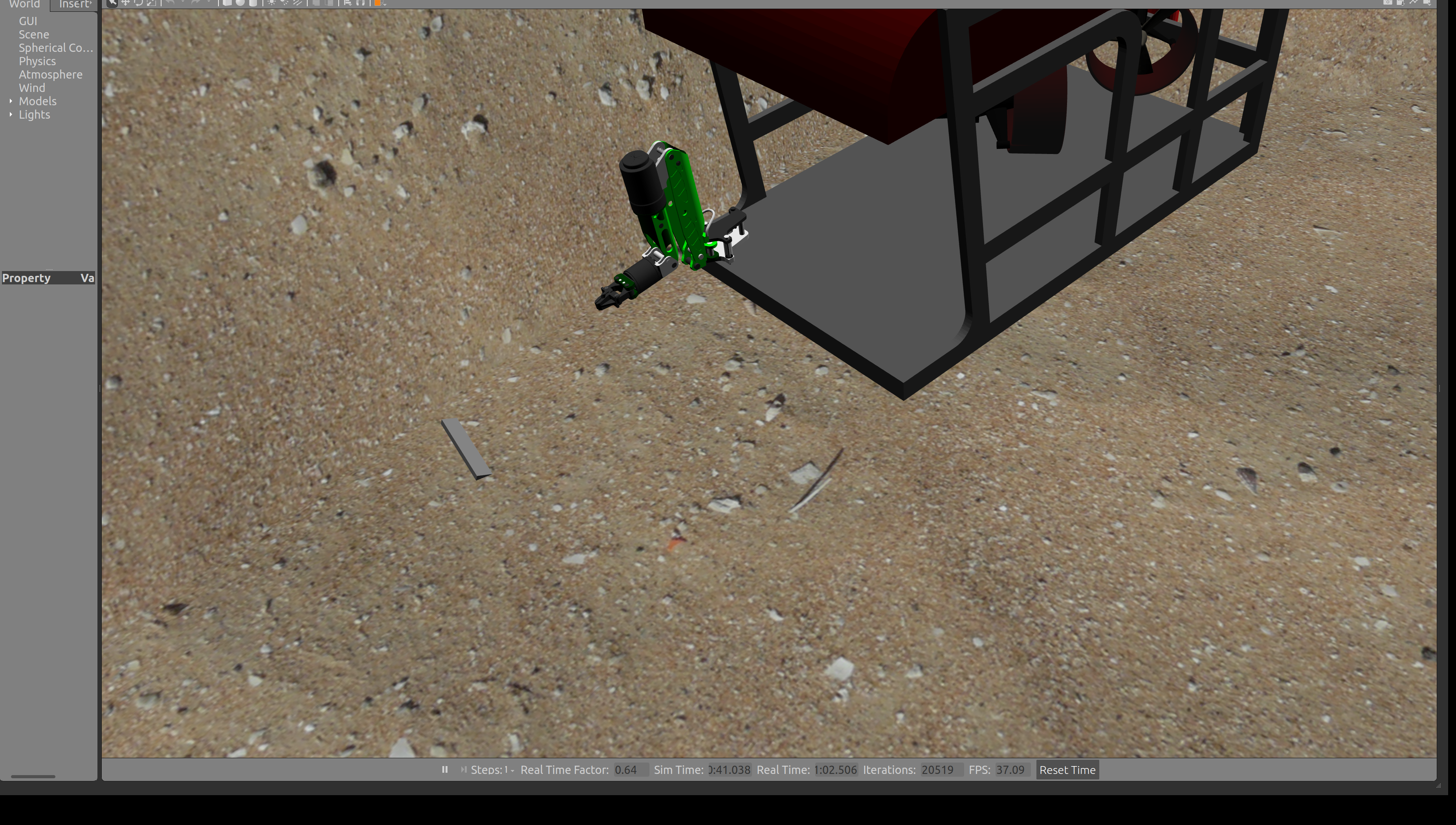
The bar in this image is partially submerged in the bottom “silt”. The effect is achieved by shifting the visual element of the model’s link in the positive Z direction by 0.1 meters (approximately 4 inches). The model itself is provided in the dave_object_models ROS package as the occluded_sand_heightmap model.
<link name="link">
  <collision name="ground">
    <pose>0 0 0 0 0 0</pose>
    <geometry>
      <mesh><uri>model://occluded_sand_heightmap/meshes/heightmap.dae</uri></mesh>
    </geometry>
  </collision>
  <visual name="ground_sand">
    <cast_shadows>true</cast_shadows>
    <pose>0 0 0.1 0 0 0</pose>
    <geometry>
      <mesh><uri>model://occluded_sand_heightmap/meshes/heightmap.dae</uri></mesh>
    </geometry>
    ...
  </visual>
</link>
In this case, the “sand” is implemented as a mesh rather than as a heightmap, but the linear shift provides the desired effect because no models with which we are concerned are expected to be on the “other side” of the “bottom (i.e., the vehicle will never be on the side of the model in which the visual component is inside the collision component). This approach will also work for terrain specified using a heightmap.
Object occlusion:
Upon launch of the simulation, a large cinderblock is located to the left of the RexRov vehicle. The cinderblock is occluded by a thin layer of visual “moss”. The following image shows the RexRov’s manipulator interacting with the cinderblock. Of note, the end of the manipulator is partially obscured by the occlusion, and it is pushing the cinderblock by interacting with the model’s collision element.
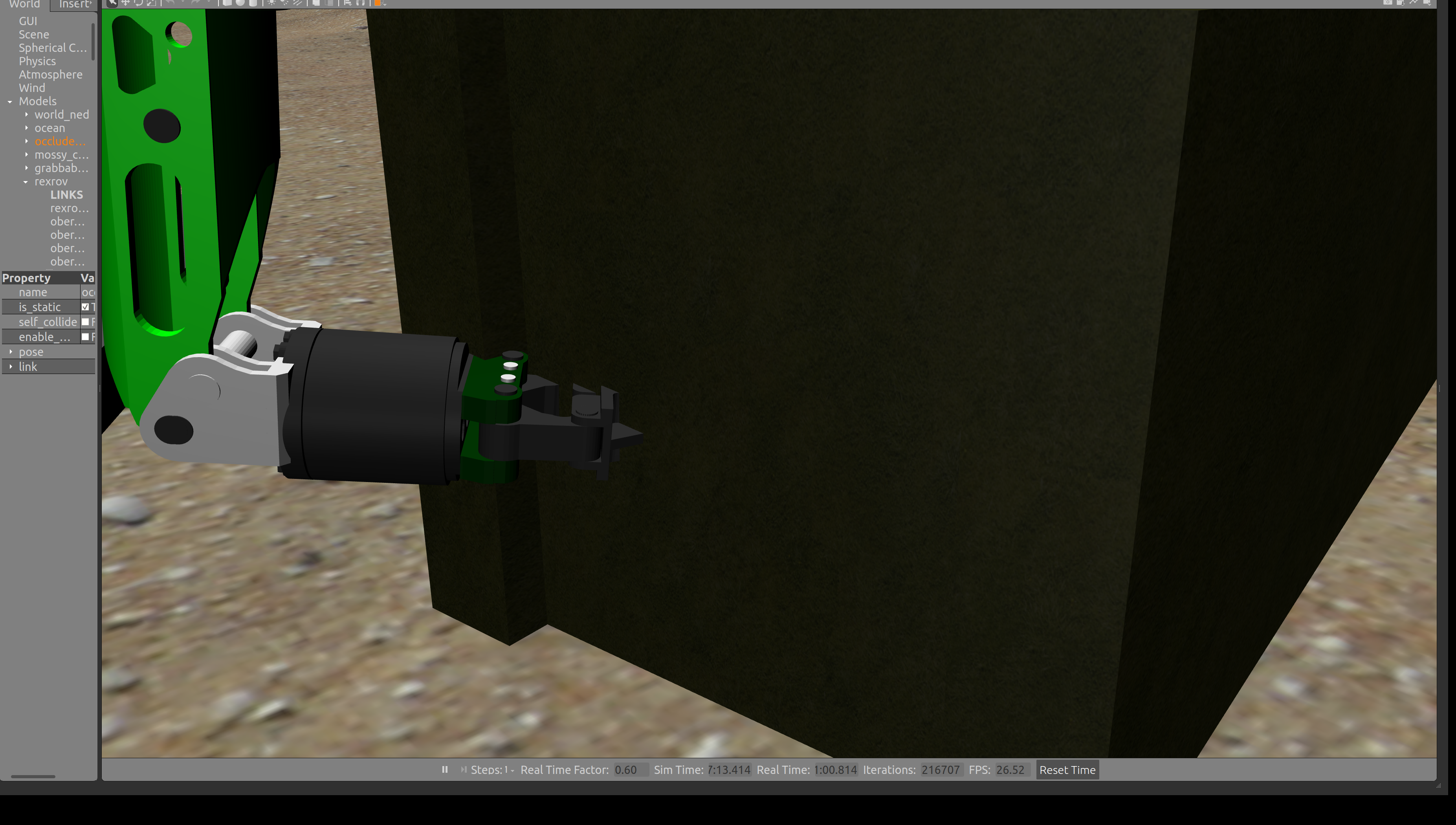
Unlike terrain, occlusion cannot be implemented on models such as this one with a linear shift of the visual element. Rather, visual occlusion on all sides is achieved by increasing the scale of the visual model as indicated in the following snippet from the dave_object_models/mossy_cinder_block model.
<link>
  <visual name="visual">
    <geometry>
      <mesh>
        <scale>1.1 1.1 1.1</scale>
        <uri>model://mossy_cinder_block/meshes/mossy_cinder_block.dae</uri>
      </mesh>
    </geometry>
  </visual>
  <collision name="left">
    <pose>0 -0.25395 0.3048 0 0 0</pose>
    <geometry>
      <box>
        <size>1.30485 0.1017 0.6096</size>
      </box>
      ...
    </geometry>
  </collision>
  ...
</link>
The scale for this particular model is 1.1 in all three axes. The collision model is approximately 1.3 meters in length, 0.75 meters in width, and 0.3 meters high, so the depth of the occlusion varies (uniform occlusion requires varying the scale of the visual model with each axis). In general, the amount of scaling required to achieve a specific depth of occlusion using this technique will vary with the size of the model (i.e., larger models will achieve the same depth of occlusion with smaller visual scale increases than smaller models).
Mud plugin demo
Start the demo for bottom occlusion with damping via the following command:
roslaunch dave_demo_launch dave_mud_demo.launch
The command will launch a world similar to the basic occlusion demo, and the vehicle can be controlled in the same manner. A paddle-shaped object is available for manipulation, and a “mud pit” has been added around the spawned models. Grasp the object and move the vehicle around the area, observing the difference in motion when the paddle is partially submerged in the mud vs. moving unobstructed through the water.
This image shows the vehicle moving with the paddle well above the mud pit. Note the near-vertical attitude.

The image below shows the difference in behavior when the vehicle drags the paddle through the simulated viscous material.

In order to make the effects of the mud pit easier to observe, this demonstration includes exaggerated features: the offset between the solid bottom and the occluded layer is increased to 0.5 meter, the object for manipulation has a large surface area, and a high damping coefficient is selected. A visual element has been added as well.
As with the purely visual occlusion, we create a new model from the seafloor mesh. In this demo, the model is given depth to improve its appearance, and its spatial extent is a small portion of the overall seafloor. Limiting the size of the mud pit improves simulation performance. It also makes it possible to simulate different bottom materials, with different damping coefficients in each section.
The model must contain a collision element in order to calculate its interactions with other objects, but the two models must be able to occupy the same space. This is accomplished by including <collide_without_contact>true</collide_without_contact> in the collision element of the sdf. A visual element is optional.
The motion damping is implemented via the gazebo_mud plugin, which creates a temporary artificial joint between the mud object and all links which are tagged to interact with the mud, and a contact sensor.
<link name="link">
   …
  <sensor name="mud_contact" type="contact">
    <always_on>true</always_on>
    <update_rate>1000</update_rate>
    <contact>
      <collision>collision</collision>
    </contact>
  </sensor>
</link>
<plugin name="gazebo_mud" filename="libMudPlugin.so">
  <contact_sensor_name>link/mud_contact</contact_sensor_name>
  <stiffness>0.0</stiffness>
  <damping>20.0</damping>
  <link_name>mud_anchor::drag_anchor</link_name>
</plugin>
Because this implementation uses the <collision> element, unlike the simpler visual method above, sensors that use collision checking will react to the new surface. If this is not the desired behavior, it is possible to filter collisions using <collide_without_contact_bitmask>.