Page last modified: Aug 17 2021.
Tutorial: DVL Examples (ROS Package)
Overview
The ROS dave_sensor_models package provides SDF models for utilization, testing, and evaluation of the UUV Simulator and Woods Hole Oceanographic Institute (WHOI) Deep Submergence Laboratory (DSL) environment ROS Doppler Velocity Logger (DVL) plugins. The plugin parameters of the exemplars’ utilized in this tutorial roughly align with the specifications of the Teledyne Workhorse Navigator (WHN) 600 DVL. Model and world files can be used as is for testing of the DVL models. The dave repository also includes URDF (Xacro) files for use in adding DVLs to arbitrary Gazebo robot models and worlds. Xacro files are located in DVL-model-specific _description packages in the urdf/sensors directory.
Models and Xacro files are provided for the following DVLs:
- Nortek DVL 500-300m
- Nortek DVL 500-6000m
- Nortek DVL 1000-300m
- Nortek DVL 1000-4000m
- Sonardyne Syrinx 600
- Teledyne Explorer 1000 (Phased Array)
- Teledyne Explorer 4000 (Piston)
- Teledyne WHN 600
These templates can be utilized in a manner similar to the WHN examples of this tutorial.
UUV Simulator Plugin Utilization
The dave_sensor_launch and dave_demo_launch packages each contain a launch file that can be run independently to (both covered in more detail below) to launch DVL models utilizing the UUV Simulator DVL plugin. These can be executed with the following commands:
roslaunch dave_sensor_launch teledyne_whn_uuvsim_demo.launch
OR
roslaunch dave_demo_launch dave_dvl_demo_uuvsim.launch
Once Gazebo is up, choosing to “Follow” the teledyne_whn or caldus model respectively simplifies the visualization.
URDF models and Xacro macros for use in implementing the WHN DVL in other Gazebo simulations are contained in the teledyne_whn_uuvsim_description package.
teledyne_whn_uuvsim_demo.launch
Launch and Operation
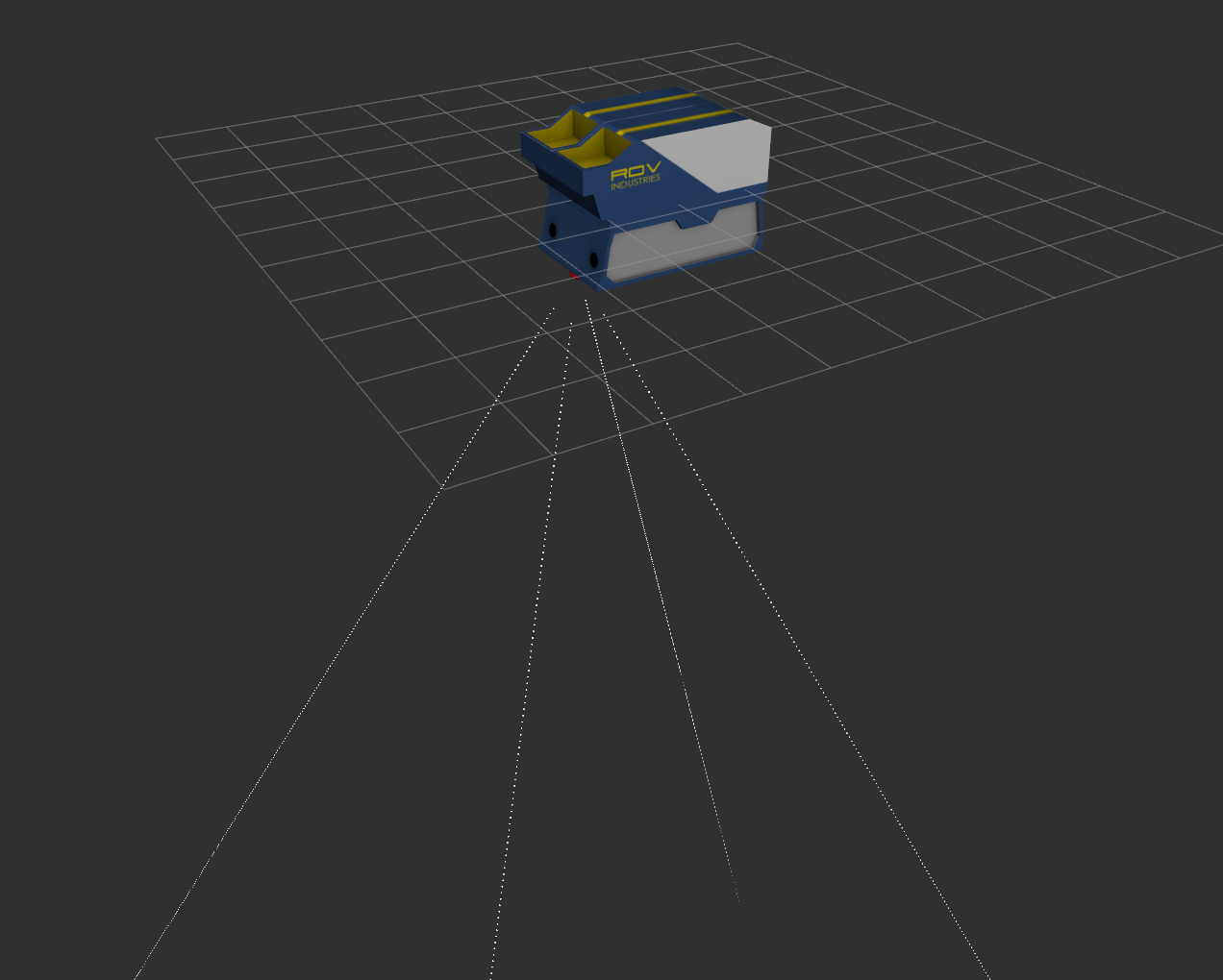
The teledyne_whn_uuvsim_demo.launch file instantiates a Gazebo world (by default, the dave_worlds/ocean_waves.world) containing a single Teledyne DVL attached to a dimensionless link (the DVL is not within the world’s camera field of view, but the it is located just below the water’s surface near the model’s center as depicted below).
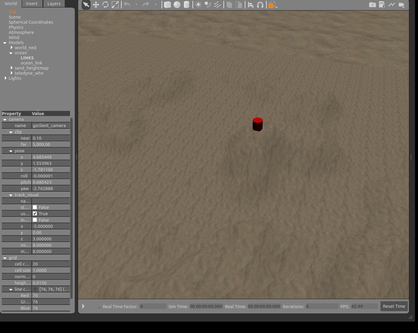
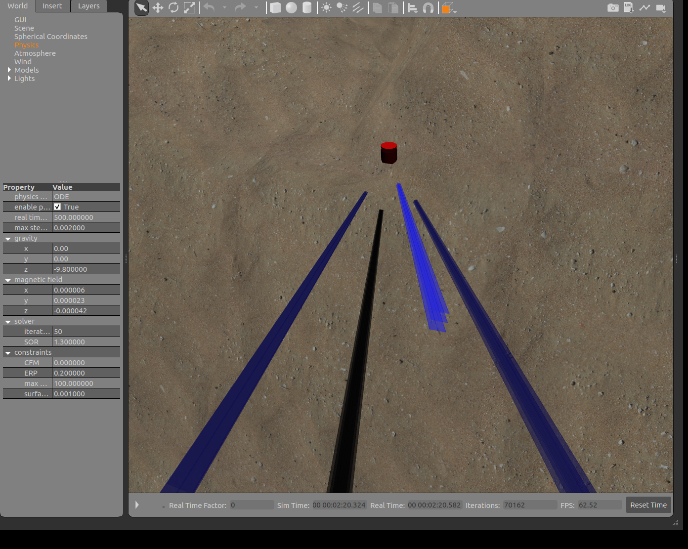
After approximately 10 seconds, the DVL will begin moving in a descending left-handed octagon pattern. It will continue with this pattern until impacting the bottom. During its descent, the DVL sonar beam visualization will indicate its perceived height above the bottom.
The following launch arguments can be used to modify the execution:
- gui (default
true): set to false to run the simulation without the GUI or rendered scene. - paused (default
false): set to true to start the simulation with physics paused (can be unpaused and repaused with the/gazebo/pause_physicsand/gazebo/unpause_physicsservices respecively. - world_name (default
uuv_gazebo_worlds/worlds/ocean_waves.world): used to change the world model that is used when the simulation commences.
ROS Topics
The following ROS topics are relevant:
- /dvl/dvl/state (
std_msgs/Bool): should be true as long as the DVL is active (can be activated and deactivated with the/dvl/dvl/change_stateservice). - /dvl/dvl (
uuv_sensor_ros_plugins_msgs/DVL): provides the current DVL-derived linear velocities (relative to thedvl_base_link, which is oriented forward-left-up) and covariance, perceived altitude above the bottom (computed as the average of the 4 individual sonar ranges), and the ranges and other information for the 4 individual DVL sonar beams. - /dvl/dvl_twist (
geometry_msgs/TwistWithCovarianceStamped): provides the current DVL-derived linear velocities - /dvl/dvl_sonar0, /dvl/dvl_sonar1, /dvl/dvl_sonar2, and /dvl/dvl_sonar3 (
sensor_msgs/Range): Range and other information for each individual DVL sonar.
ROS Nodes
spawn_whn (
gazebo_ros/spawn_model)The
spawn_whnnode is used to spawn the standalone WHN600 model in the gazebo world. Once the model has been spawned, this node will terminate.apply_velocity (
nps_uw_sensors_gazebo/simple_motion.py)The
apply_velocitynode publishes periodicgazebo_msgs/ModelStatemessages to the/gazebo/set_model_statetopic to control the motion of the DVL model through a descending octabonal pattern (fixed linear speed of 1 meter per second, vertical speed of between 0.2 and -0.4 meters per second). The model name and frame to which the new state is relative are provided as ROS parameters (set in the launch file). The frame of relative motion should be the model’s base link to ensure correct motion.joint_state_publisher (
joint_state_publisher/joint_state_publisher)The
joint_state_publishernode continually publishes the state of the model’s joints to the/joint_statestopic as it moves through the world so that they will be available to the robot state publisher.robot_state_publisher (
robot_state_publisher/robot_state_publisher)The
robot_state_publishernode subscribes to the/joint_statestopic and publishes transforms to the/tftopic. The DVL plugin uses the transforms associated with the 4 DVL sonar beams in its calculations.
See launch file for additional information regarding parameters and arguments.
dave_dvl_demo_uuvsim.launch
Launch and Operation
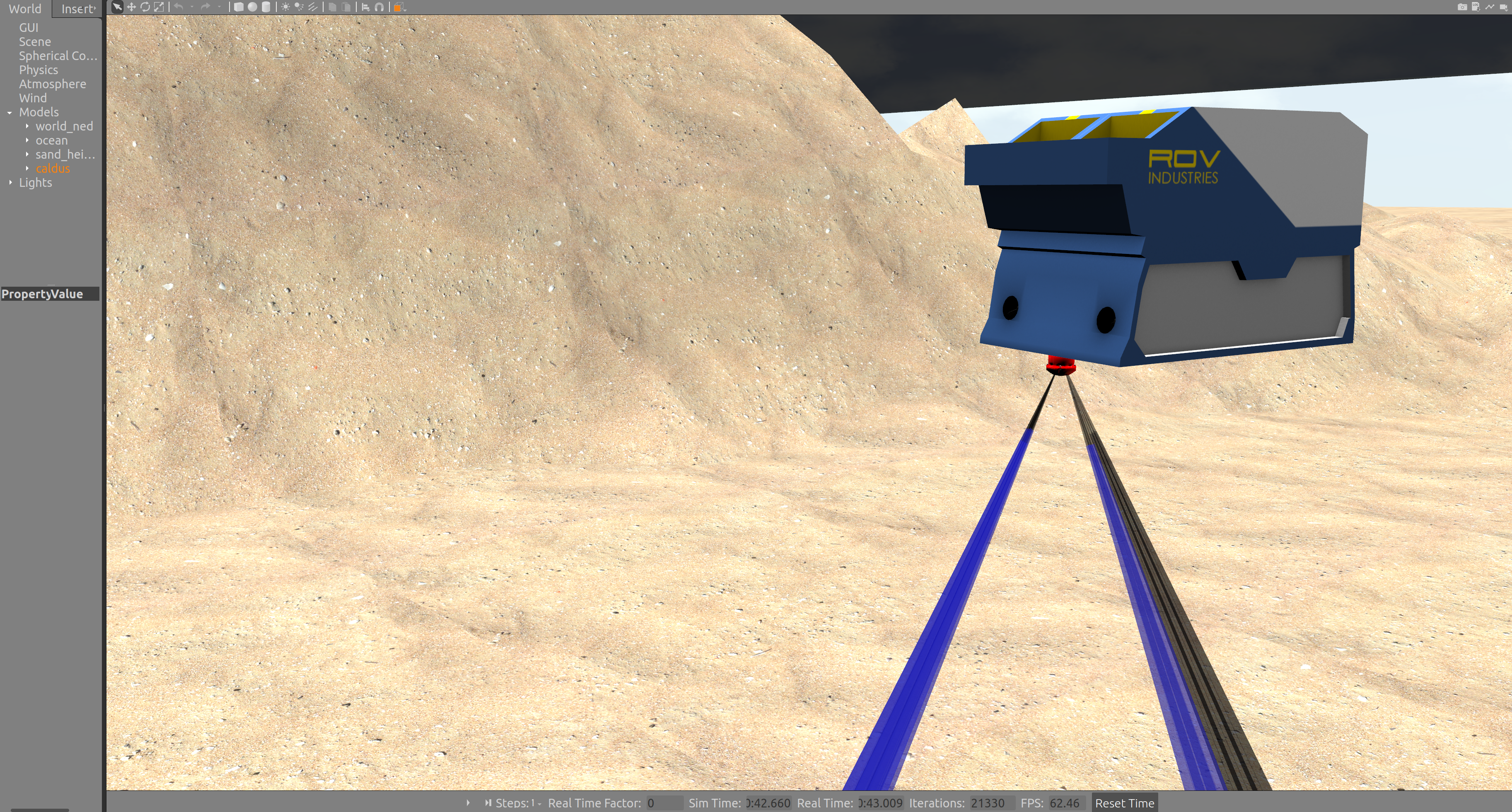
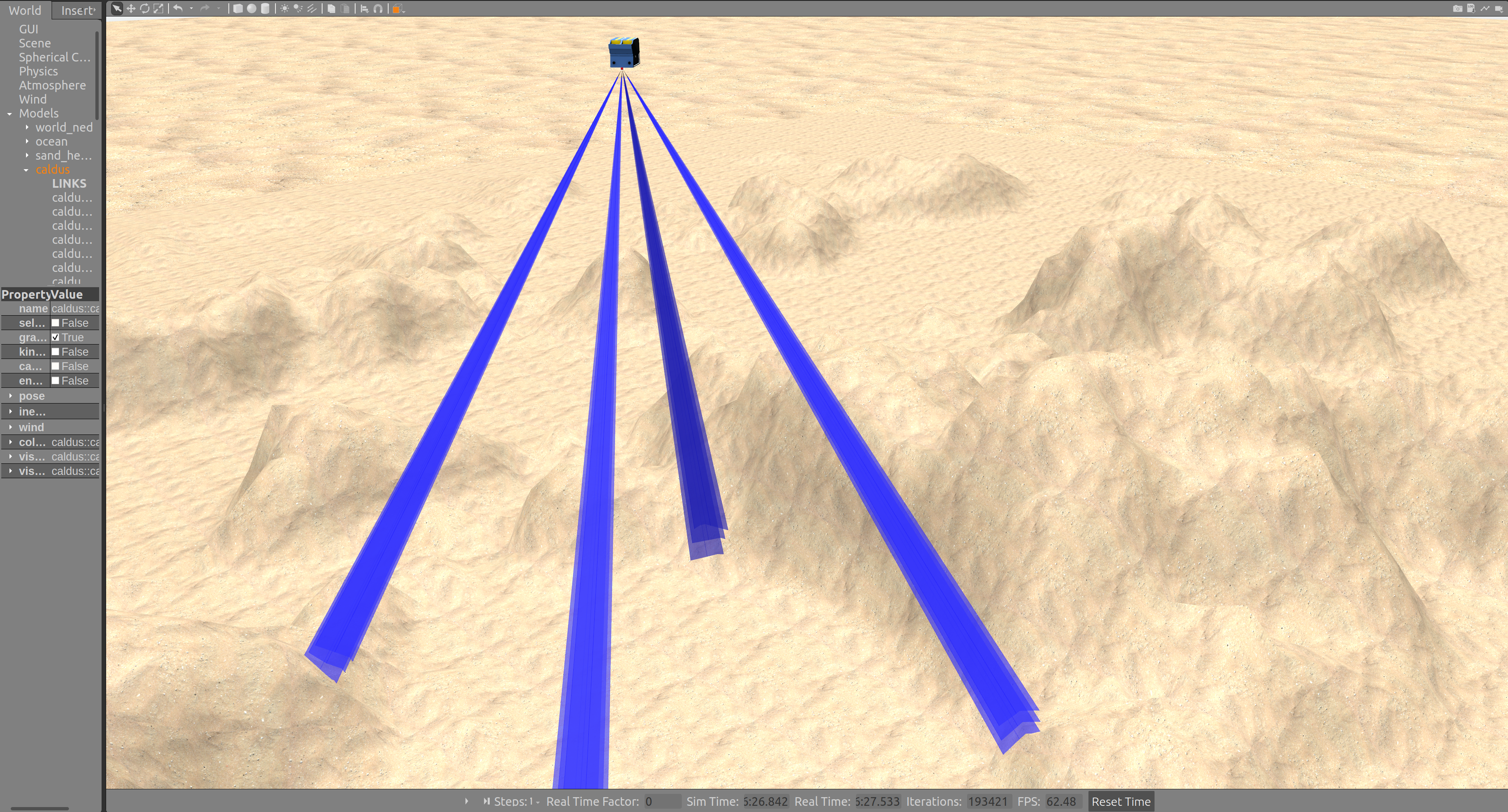
The dave_dvl_demo_uuvsim.launch file uses macros from a teledyne_whn_uuvsim_description package Xacro file to generate a WHN600 DVL model mounted on a medium-sized UUV (the Caldus UUV from the caldus_description package). As with the standalone DVL example, the model is not within the world’s camera field of view, but can be located by choosing to “Follow” or “Move to” the caldus model once the simulation is running.
The UUV can be maneuvered using the Logitech F310 Gamepad or other joystick.
Launch arguments are the same as with the standalone WHN600 example. Relevant ROS topics are the same as well except that they are in the caldus vice dvl namespace (e.g., /caldus/dvl for the DVL-derived velocities, covariances, and altitudes). ROS nodes are similar to those of the standalone WHN600 example except that a spawn_caldus node is used to generate the robot model and the joy_thrusterop.launch file from the dave_nodes package is used to launch the nodes associated with joystick control.
UUV Simulator Models and Macros
Teledyne WHN Model (models/dave_sensor_models/models/teledyne_whn_uuvsim/model.sdf)
The teledyne_whn_uuvsim model is a self-contained implementation of the Teledyne WND600 DVL in SDF format. This model can be included in any SDF world and connected to a robot in that world through a joint connecting the model’s dvl_link to the robot’s base link.
In order for the DVL plugin to work correclty, it must have access to the ROS transforms for the robot link to which it is attached. Because SDF is not compatible with the ROS robot state publisher, the transforms must be published from a different source (most likely from the robot’s controller plugin).
Teledyne WHN Macros
teledyne_whn.xacro
The
teledyne_whn_uuvsim_descriptionpackageurdf/teledyne_whnXacro file provides a set of macros for the addition of a Teledyne WHN600 DVL to an arbitrary Xacro-generated robot model (seeurdf/uuvsim_teledyne_whn.xacrofor a simple example). Four top-level macros are provided:- teledyne_whn_macro: provides for the generation of a DVL model with a user-specified namespace, parent link (robot base link), inertial reference frame, and origin relative to the inertial reference frame. Parameters are as follows: – namespace: string namespace in which all of the links and ROS topics reside. – parent_link: robot link to which the sensor link will be attached. – inertial_reference_frame: static reference frame (i.e., world frame) in which the robot maneuvers. – *origin: block parameter for the location of the DVL sensor link on the robot.
- teledyne_whn_sensor_enu: provides for the generation of a DVL model in an east-north-up inertial reference frame (i.e., the default Gazebo frame) by invoking the
teledyne_whn_macromacro with appropriate parameters (the examples of this tutorial utilize this macro). Parameters are as follows: – namespace: string namespace in which all of the links and ROS topics reside. – parent_link: robot link to which the sensor link will be attached. – *origin: block parameter for the location of the DVL sensor link on the robot. - teledyne_whn_sensor_ned: provides for the generation of a DVL model in an north-east-down inertial reference frame (i.e., the default Gazebo frame) by invoking the
dvl_macromacro with appropriate parameters. The NED frame must be explicitly defined or included in the world model (seedave_ocean_waves.worldfrom thedave_worldspackage) for models generated with this macro to function properly. Parameters are as follows: – namespace: string namespace in which all of the ROS topics reside. – parent_link: robot link to which the sensor link will be attached. – *origin: block parameter for the location of the DVL sensor link on the robot. - dvl_plugin_macro: provides for the generation of a DVL model with user-specified namespace, suffix (sensor ID), parent link, individual sonar ROS topic names, visual scale, update rate, sensor noise parameters, inertial reference frame, and origin relative to the inertial reference frame. This macro provides the most flexibility and can be used to model most real-world DVLs. The
teledyne_whn_macromacro is essentially a wrapper for this macro and can be used as an example for its use. Parameters are as follows: – namespace: string namespace in which all of the links and ROS topics reside. – suffix: arbitrary identifying suffix that is added to all joint and link names. – parent_link: robot link to which the sensor link will be attached. – topic: ROS topic to which DVL sensor messages are to be published. – update_rate: rate at which DVL sensor messages are to be published (Hz). – reference_frame: static reference frame (i.e., world frame) in which the robot maneuvers. – *noise_sigma: standard deviation of the velocity solution (only used for covariance matrix computation). – noise_amplitude: standard deviation of the Gaussian noise added to each of the computed linear velocity vectors. – *origin: block parameter for the location of the DVL sensor link on the robot.
teledyne_whn_standalone.xacro
The
teledyne_whn_uuvsim_descriptionpackageurdf/teledyne_whn_standaloneXacro file utilizes the macros provided inteledyne_whn.xacroto create with a single WHN600 DVL attached to a dimensionless link. The resulting URDF model is suitable for upload to the ROS parameter server for subsequent insertion into Gazebo scenes. This macro is utilized by thedave_sensor_launch/teledyne_whn_uuvsim_demo.launchdescribed above.
Additional Macro Files
The following Xacro files are provided for the generation of URDF UUV Simulator plugin models for different commercially available DVLs. Each provide the same top-level macros as the teledyne_whn_uuvsim_description package urdf/teledyne_whn.xacro and implement sensor characteristics as specified in the vendor-provided datasheets. They can be utilized in the same manner as the macros in urdf/teledyne_whn.xacro.
- Nortek DVL500-300m (located in the
nortek_dvl500_300_uuvsim_descriptionpackage) - Nortek DVL500-6000m (located in the
nortek_dvl500_6000_uuvsim_descriptionpackage) - Nortek DVL1000-300m (located in the
nortek_dvl1000_300_uuvsim_descriptionpackage) - Nortek DVL1000-4000m (located in the
nortek_dvl1000_4000_uuvsim_descriptionpackage) - Sonardyne Syrinx 600 (located in the
sonardyne_syrinx600_uuvsim_descriptionpackage) - Teledyne Explorer 1000 (Phased Array) (located in the
teledyne_explorer1000_uuvsim_descriptionpackage) - Teledyne Explorer 4000 (Piston) (located in the
teledyne_explorer4000_uuvsim_descriptionpackage)
Woods Hole Oceanographic Institute Deep Submergence Lab Environment Plugin Utilization
The WHOI Deep Submergence Lab (DSL) environment plugins require the ds_sim and ds_msgs ROS packages, both of which are available at https://bitbucket.org/whoidsl/. The nps_dev branch of the NPS-maintained versions of these repositories (https://github.com/Field-Robotics-Lab/ds_sim and https://github.com/Field-Robotics-Lab/ds_msgs respectively) provide additional capabilities (e.g., water tracking) described below.
The dave_sensor_launch and dave_demo_launch packages each contain a launch file that can be run independently to (both covered in more detail below) to launch DVL models utilizing the WHOI DVL plugin. These launch files function similarly to those launching the UUV Simulator plugin models and can be executed with the following commands:
roslaunch dave_sensor_launch teledyne_whn_dsl_demo.launch
OR
roslaunch dave_demo_launch dave_dvl_demo_dsl.launch
As with their UUV Simulator counterparts, choosing to “Follow” teledyne_whn or caldus model respectively will simplify the visualization.
URDF models and Xacro macros for use in implementing the WHN DVL in other Gazebo simulations are contained in the teledyne_whn_dsl_description package.
teledyne_whn_dsl_demo.launch
Launch and Operation
The teledyne_whn_dsl_demo.launch file instantiates a Gazebo world (dave_worlds/ocean_waves.world by default) containing a single Teledyne DVL attached to a dimensionless link (the DVL is not within the world’s camera field of view, but the it is located just below the water’s surface near the model’s center as depicted below).
After approximately 10 seconds, the DVL will begin moving in a descending left-handed octagon pattern. It will continue with this pattern until impacting the bottom. The simulation will proceed as depicted in the figures above except that the individual sonar beams will not be visible.
Available launch arguments are the same as described for previous launch files.
ROS Topics
The following ROS topics are relevant:
- /whn/dvl (
ds_sensor_msgs/Dvl): Provides current DVL sensor status and information. Information that is correctly represented are linear velocity and covariance, individual sonar ranges and covariance, individual sonar beam unit vectors (in the DVL reference frame). Additional message fields are either not currently implemented by the sensor or plugin (e.g., raw velocity and covariance) or are fixed to align with static sensor and plugin implementations (e.g., velocity_mode, coordinate_mode, and dvl_type). - /whn/dvl_ranges (
ds_sensor_msgs/Ranges3D): Provides current range information for each of the DVL’s sonar beams. Information includes range quality and validity metrics, and a 3D point in the DVL reference frame corresponding to its return range (out to maximum range). - /whn/dvl_cloud (
sensor_msgs/PointCloud): Point cloud representation of the individual DVL beams. The published point cloud does not provide any representation of the current ranges or velocities, but can be used to ensure proper pose relative to a robot body (e.g., using RVIZ). - /whn/dvl_current (
ds_sensor_msgs/Adcp): Provides current water tracking data in Acoustic Doppler Current Profiler (ADCP) format. Velocity is provided for evenly spaced “bins” at depths relative to the sensor out to the maximum range (e.g., every 8 meters). For each depth, water track linear velocity is provided as a single 3-vector multiple beam-specific 3-vectors.
ROS Nodes
Unlike the UUV Simulator plugin, the WHOI model does not rely on externally generated transforms to function properly. Rather, it relies on a custom Gazebo sensor. This implementation obviates the requirement for joint_state_publisher or robot_state_publisher nodes. Other nodes are the same as those from the UUV Simulator examples.
See launch file for additional information regarding parameters and arguments (including the Gazebo parameters for inclusion of the ds_sim DVL sensor).
Water Tracking
Current-affected water tracking can be tested and observed using the teledyne_whn_dsl_demo.launch file if the nps_dev branch of the NPS-maintained ds_sim repository is used (origin repository pull request pending).
roslaunch dave_sensor_launch teledyne_whn_dsl_demo.launch
The water tracking implementation is described in the DVL description wiki. The default water tracking characteristics noted in the wiki are utilized here.
Water tracking utilizes gazebo::msgs::vector3D messages published to a Gazebo ocean current topic. This information is also published on the ROS network as on the topic /hydrodynamics/current_velocity. The Gazebo world invoked by teledyne_whn_dsl_demo.launch incorporates the UUV Simulator ocean current plugin for this purpose.
After launch rqt_graph can be used to plot vehicle velocity, current velocity, and the DVL’s water tracking solution:
rqt_plot /whn/dvl/velocity/x /whn/dvl/velocity/y /gazebo/model_states/twist[3]/linear/x /gazebo/model_states/twist[3]/linear/y /hydrodynamics/current_velocity/twist/linear/x /hydrodynamics/current_velocity/twist/linear/y
The ocean current velocity is set to 0 at launch, so vehicle velocity and the DVL solution will be aligned. Current can be arbitrarily reset using ROS services as described in ocean current plugin). E.g.,
rosservice call /hydrodynamics/set_current_velocity "velocity: 1.0
horizontal_angle: 0.0
vertical_angle: 0.0"
After changing the current the plotted DVL solution diverge from the vehicle’s actual velocity according to the difference between vehicle and current velocities (vehicle velocity is externally controlled for this demonstration and will be unaffected). The following plot was obtained with a current velocity of 0.5 meters per second at a horizontal angle of 0.8 and vertical angle of 0.0.
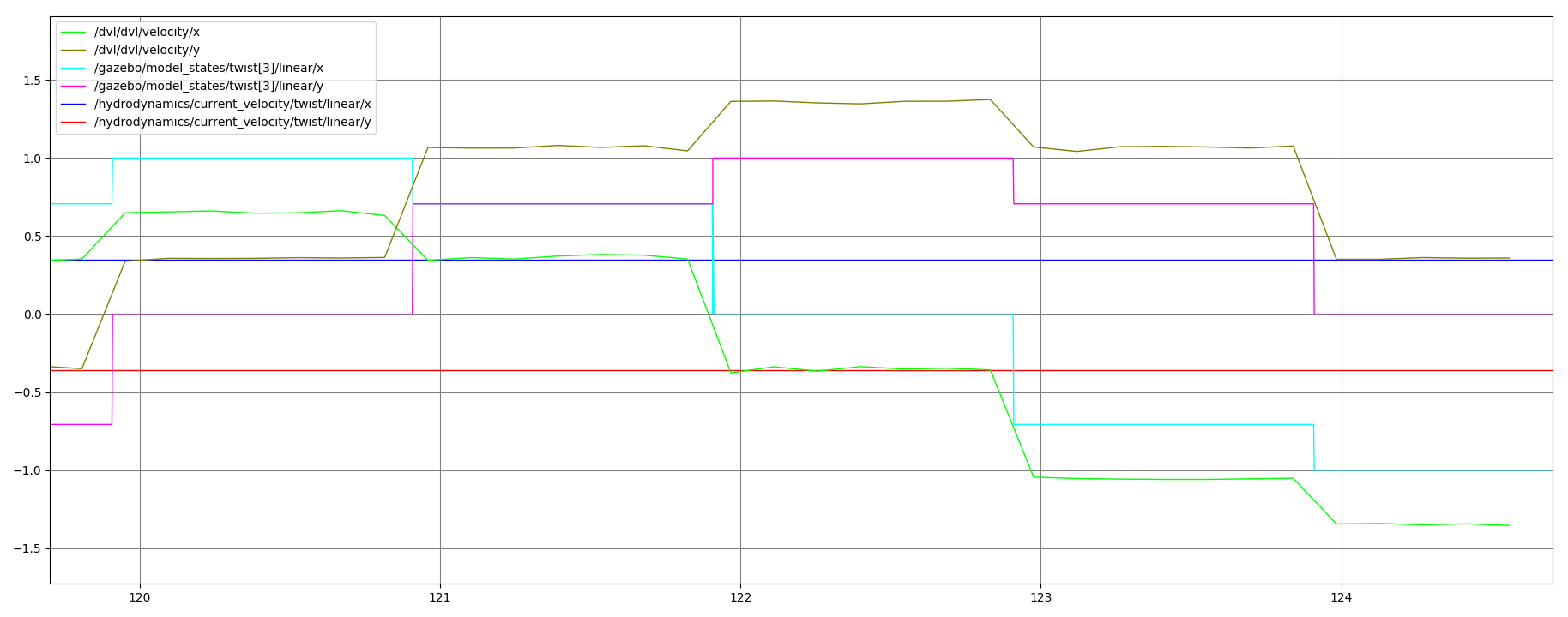
The DVL plugin only provides a water tracking solution when a bottom tracking solution is unavailable. With this launch file, the vehicle is near enough to the surface that the bottom is initially beyond the range of the DVL beams. When the vehicle’s descent brings it close enough to the bottom, the solution will automatically switch from water tracking to bottom tracking. This will be noted in rqt_plot by alignment of the vehicle velocity and DVL solution and in the published ds_sensor_msgs/Dvl message velocity_mode field (1 indicates bottom tracking, 2 indicates water tracking).
To verify that the transition between water-tracking and bottom-tracking happens, plot the seafloor height, dvl height and velocity_mode.
rqt_plot /gazebo/model_states/pose[2]/position/z /gazebo/model_states/pose[3]/position/z /dvl/dvl/velocity_mode
dave_dvl_demo_dsl.launch
Launch and Operation
The dave_dvl_demo_dsl.launch file uses macros from a teledyne_whn_dsl_description package Xacro file to generate a WHN600 DVL model mounted on a medium-sized UUV (the Caldus UUV from the caldus_description package). As with the standalone DVL example, the model is not within the world’s camera field of view, but can be located by choosing to “Follow” or “Move to” the caldus model once the simulation is running.
The UUV can be maneuvered using the Logitech F310 Gamepad or other joystick.
Launch arguments are the same as with the standalone WHN600 example. Relevant ROS topics are the same as well except that they are in the caldus vice whn namespace (e.g., /caldus/dvl for the DVL-derived velocities, covariances, and altitudes). ROS nodes are similar to those of the standalone WHN600 example except that a spawn_caldus node is used to generate the robot model and the joy_thrusterop.launch file from the dave_nodes package is used to launch the nodes associated with joystick control.
ROS Nodes
Launching ROS with the dave_dvl_demo_dsl.launch file invokes all of the ROS nodes described in the dave_dsl_demo_uuvsim.launch section of this tutorial. An rviz node is started to visualize the point cloud generated by the DVL plugin (the configuration is loaded from the rviz/whoi_teledyne_dvl.rviz in the teledyne_whn_dsl_description package). joint_state_publisher and robot_state_publisher nodes have been included as well to facilitate RViz utilization.
The RViz visualization does not provide any sensed information, but the displayed point cloud can be used to verify the correct placement and orientation of the DVL on the robot.
Water tracking can be tested and observed with this macro as previously described.
WHOI DSL Models and Macros
Teledyne WHN Model (models/dave_sensor_models/models/teledyne_whn_dsl/model.sdf)
The teledyne_whn_dsl model is a self-contained implementation of the Teledyne WND600 DVL in SDF format. This model can be included in any SDF world and connected to a robot in that world through a joint connecting the model’s whn_base_link to the robot’s base link. Because the WHOI DSL environment implements a custom Gazebo DVL sensor rather than relying on embedded Ray sensors, this model’s plugin does not require access to externally generated transforms and will work as is. It does however require the dsros_sensors library to be loaded when Gazebo is started (see tutorial launch files for load command).
Teledyne WHN Macros (urdf_whoi/teledyne_whn.xacro)
teledyne_whn.xacro
The
teledyne_wyn_dsl_descriptionpackageurdf/teledyne_whnXacro file provides a set of macros for the addition of a Teledyne WHN600 DVL to an arbitrary Xacro-generated robot model. A single top-level macro is provided:- teledyne_whn_macro: provides for the generation of a DVL model with a user-specified parameters. The macro generates the DVL link, its sensor (both the Gazebo sensor element and plugin), and the joint attaching the DVL to a robot. Parameters are as follows: – name: string name of the sensor that will be incorporated into link, joint, and sensor names. – namespace: string namespace in which all of the ROS topics reside. – xyz: location on the DVL link at which the visual and collision elements are centered (inertial is centered on the origin). – dvl_topic: ROS topic to which DVL sensor messages will be published. – ranges_topic: ROS topic to which consolidated sonar beam range messages will be published. – robot_link: robot link to which the sensor link will be attached. – joint_xyz: position on the robot to which the DVL is to be mounted.
teledyne_whn_standalone.xacro
The
teledyne_wyn_dsl_descriptionpackageurdf/teledyne_whn_standaloneXacro file utilizes the macro provided inteledyne_whn.xacroto create with a single WHN600 DVL attached to a dimensionless link. The resulting URDF model is suitable for upload to the ROS parameter server for subsequent insertion into Gazebo scenes. This macro is utilized by thedave_sensor_launch/teledyne_whn_dsl_demo.launchdescribed above.Additional Macro Files
The following Xacro files are provided for the generation of URDF WHOI DSL plugin models for different commercially available DVLs. Each provides the same top-level macro as the
teledyne_whn_dsl_descriptionpackageurdf/teledyne_whn.xacroand implement sensor characteristics as specified in the vendor-provided datasheets. They can be utilized in the same manner as the macros inurdf/teledyne_whn.xacro.- Nortek DVL500-300m (located in the
nortek_dvl500_300_dsl_descriptionpackage) - Nortek DVL500-6000m (located in the
nortek_dvl500_6000_dsl_descriptionpackage) - Nortek DVL1000-300m (located in the
nortek_dvl1000_300_dsl_descriptionpackage) - Nortek DVL1000-4000m (located in the
nortek_dvl1000_4000_dsl_descriptionpackage) - Sonardyne Syrinx 600 (located in the
sonardyne_syrinx600_dsl_descriptionpackage) - Teledyne Explorer 1000 (Phased Array) (located in the
teledyne_explorer1000_dsl_descriptionpackage) - Teledyne Explorer 4000 (Piston) (located in the
teledyne_explorer4000_dsl_descriptionpackage)
- Nortek DVL500-300m (located in the